Electronic Throttle Bodies
The Throttle Body on an internal combustion engine controls the amount of air that enters the engine and as a result controls the engine speed. This was traditionally achieved by connecting a cable from the accelerator pedal directly to the throttle body.
As engine management systems have evolved over the years the cable throttle body has been replaced by the electronic throttle body. Commonly known as drive by wire it is now fitted by to the majority of vehicles on the road today. Electronic Throttle Control Systems rely on three main components
- 1. Accelerator Pedal Position Sensor
- 2. Power train Control Module (PCM or ECM)
- 3. Electronic Throttle body
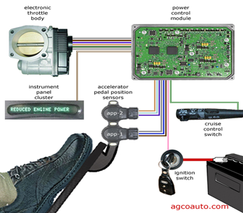
Some systems also incorporate an Electronic Throttle Control Module.
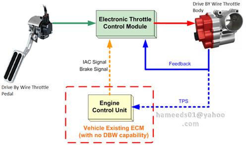
The “drive by wire system” has been used by vehicle manufacturers since 1988 when BMW introduced it on the 7 series. There are variations in how different electronic throttle bodies operate depending on brand and application. It is important to refer to the appropriate workshop information for the specific vehicle you are working on. The actuator (electric motor) is operated by controlling the current flow thru the motor using pulse width modulation. The voltage applied to the DC electric motor is in the form of a square wave. The DC electric motor responds to the change in duty cycle controlled by the ECU. This signal is best measured using an oscilloscope and is usually expressed as a percentage. Eg. 50% duty cycle.
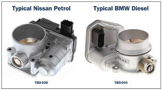
Although the Electronic Throttle Body fitted to a diesel engine looks similar to that fitted to a petrol engine the way they operate is very different.
Common Link less Type Electronic Throttle Body
This commonly used throttle body integrates the drive motor which moves the throttle valve and two TPS units are used for ECU feedback.
Advantages include
- No need for cruise control actuators or modules
- No need for a separate idle control system
- Improved drivability by controlling torque transfer when required
- Improved traction and stability control
Diesel EDR-Di Electromotive regulating throttle type system
Mainly used on Diesel engines.
- Control of EGR gasses in the engine by continuous adjustment of the throttle valve
- Avoiding shut down shakes when the engine is switched off by restricting the air flow to the engine
- The throttle valve is generally in the fully open position at rest
- A vacuum pump is required for vacuum controlled/operated components
- The throttle valve is generally not used for RPM and torque control
- May have single or double throttle position sensors integrated in these units
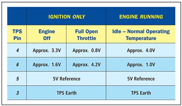
Contact type Throttle Position Sensors
Generally, dual potentiometer type unit. Each potentiometer produces opposite varying output voltages.
VE Commodore TBO-051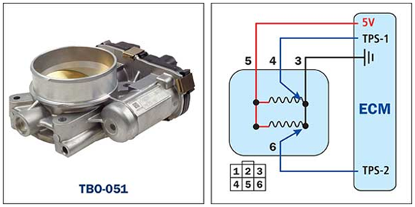
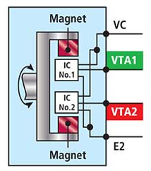
Contactless Type Throttle Position Sensors
Hall sensors for TPS output signals are utilised in some Electronic Throttle Bodies for motor cycles, light motor vehicles, heavy motor vehicles and plant and equipment. Using Hall sensors for the TPS signal reduces the effect of vibration, contamination and physical wear damage providing a constant TPS signal to the ECU. The output signal can be an analogue varying voltage signal or a digital square wave signal.
Failsafe
The system may go into failsafe mode due to a fault in the throttle circuit. This could be as a result of a fault in the pedal position sensor, associated wiring, ECU or the electronic throttle body itself.
Mechanical Failsafe
When the Electronic Throttle body harness is disconnected or the ECU power supply is interrupted the throttle valve is held open slightly in a failsafe position which allows the vehicle to be driven slowly to a workshop for repair.
Electrical Failsafe
The amount of failsafe drivability will vary depending on the manufacturer. One or more TPS or Pedal Position Sensor failures will change the vehicles drivability to ensure the safety of the passengers.
A vehicle in failsafe mode will set fault codes and illuminate the engine check light.
Testing
When testing the throttle body circuit it is important to follow the manufacturer process and specifications. If the throttle body is cleaned, removed or replaced it may be necessary to go thru a resetting procedure. If the procedure is not done according to the manufacturer instructions either manually or using a suitable scan tool poor idle control may result, including high idle, stalling etc.
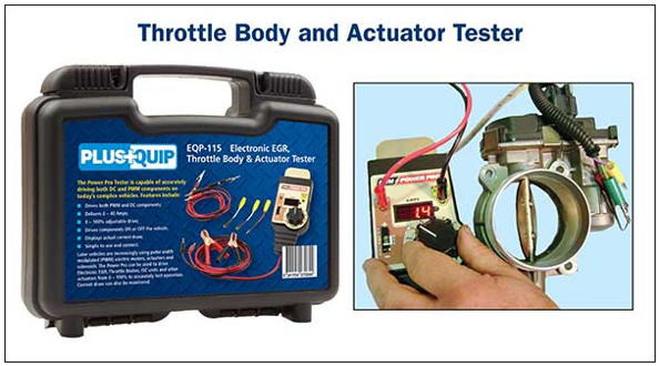
Most throttle bodies can be bench tested using the EQP-115 Electronic EGR/Throttle Body and Actuator Tester.